In brief
MIT researchers have demonstrated a system that promises to capture carbon dioxide (CO2) in various exhaust streams—from power plants to home furnaces—and even retrieve it from ambient air. At the core of their device is an electrode made of a material that grabs CO2 when the material is negatively charged and releases it the instant that charge goes away. In the device, small changes in voltage activate the electrode to capture CO2 from a passing gas stream and then release it into a subsequent stream as pure CO2 for industrial use or disposal. Tests show that the small, simple system is durable and efficient at targeting any level of CO2 in any volume of exhaust. The researchers plan to develop a pilot-scale plant within a few years.
An essential component of any climate change mitigation plan is cutting carbon dioxide (CO2) emissions from human activities. Some power plants now have CO2 capture equipment that grabs CO2 out of their exhaust. But those systems are each the size of a chemical plant, cost hundreds of millions of dollars, require a lot of energy to run, and work only on exhaust streams that contain high concentrations of CO2. In short, they’re not a solution for airplanes, home heating systems, or automobiles.
To make matters worse, capturing CO2 emissions from all anthropogenic sources may not solve the climate problem. “Even if all those emitters stopped tomorrow morning, we would still have to do something about the amount of CO2 in the air if we’re going to restore preindustrial atmospheric levels at a rate relevant to humanity,” says Sahag Voskian SM ’15, PhD ’19. And developing a technology that can capture the CO2 in the air is a particularly hard problem, in part because the CO2 occurs in such low concentrations.
The CO2 capture challenge
A key problem with CO2 capture is finding a “sorbent” that will pick up CO2 in a stream of gas and then release it so the sorbent is clean and ready for reuse and the released CO2 stream can be utilized or sent to a sequestration site for long-term storage. Research has mainly focused on sorbent materials present as small particles whose surfaces contain “active sites” that capture CO2—a process called adsorption. When the system temperature is lowered (or pressure increased), CO2 adheres to the particle surfaces. When the temperature is raised (or pressure reduced), the CO2 is released. But achieving those temperature or pressure “swings” takes considerable energy, in part because it requires treating the whole mixture, not just the CO2-bearing sorbent.
In 2015, Voskian, then a PhD candidate in chemical engineering, and T. Alan Hatton, the Ralph Landau Professor of Chemical Engineering and co-director of the MIT Energy Initiative’s Low-Carbon Energy Center for Carbon Capture, Utilization, and Storage, began to take a closer look at the temperature- and pressure-swing approach. “We wondered if we could get by with using only a renewable resource—like renewably sourced electricity—rather than heat or pressure,” says Hatton. Using electricity to elicit the chemical reactions needed for CO2 capture and conversion had been studied for several decades, but Hatton and Voskian had a new idea about how to engineer a more efficient adsorption device.
Their work focuses on a special class of molecules called quinones. When quinone molecules are forced to take on extra electrons—which means they’re negatively charged—they have a high chemical affinity for CO2 molecules and snag any that pass. When the extra electrons are removed from the quinone molecules, the quinone’s chemical affinity for CO2 instantly disappears, and the molecules release the captured CO2.
Others have investigated the use of quinones and an electrolyte in a variety of electrochemical devices. In most cases, the devices involve two electrodes—a negative one where the dissolved quinone is activated for CO2 capture, and a positive one where it’s deactivated for CO2 release. But moving the solution from one electrode to the other requires complex flow and pumping systems that are large and take up considerable space, limiting where the devices can be used.
As an alternative, Hatton and Voskian decided to use the quinone as a solid electrode and—by applying what Hatton calls “a small change in voltage”—vary the electrical charge of the electrode itself to activate and deactivate the quinone. In such a setup, there would be no need to pump fluids around or to raise and lower the temperature or pressure, and the CO2 would end up as an easy-to-separate attachment on the solid quinone electrode. They deemed their concept “electro-swing adsorption.”
The electro-swing cell
To put their concept into practice, the researchers designed the electrochemical cell shown in the two diagrams below. To maximize exposure, they put two quinone electrodes (shown in pink) on the outside of the cell, thereby doubling its geometric capacity for CO2 capture. To switch the quinone on and off, they needed a component that would supply electrons and then take them back. For that job, they used a single ferrocene electrode (shown in gray), sandwiched between the two quinone electrodes but isolated from them by electrolyte membrane separators (in white) to prevent short circuits. They connected both quinone electrodes to the ferrocene electrode using the circuit of wires at the top, with a power source along the way (indicated by the horizontal bars).
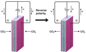
The left-hand diagram shows the system being charged. The power source creates a voltage that causes electrons to flow from the ferrocene to the quinone through the wires. The quinone is now negatively charged. When CO2-containing air or exhaust is blown past these electrodes, the quinone will capture the CO2 molecules until all the active sites on its surface are filled up.
The right-hand diagram shows the discharge cycle. The direction of the voltage on the cell is reversed, and electrons flow from the quinone back to the ferrocene. The quinone is no longer negatively charged, so it has no chemical affinity for CO2. The CO2 molecules are released and swept out of the system by a stream of purge gas for subsequent use or disposal. The quinone is now regenerated and ready to capture more CO2.
Two additional components are key to successful operation. First is an electrolyte, here a liquid salt, that moistens the cell with positive and negative ions (electrically charged particles). Since electrons only flow through the external wires, those charged ions must travel within the cell from one electrode to the other to close the circuit for continued operation.
The second special ingredient—not visible in the diagrams—is carbon nanotubes. In the electrodes, the quinone and ferrocene are both present as coatings on the surfaces of carbon nanotubes. Nanotubes are both strong and highly conductive, so they provide good support and serve as an efficient conduit for electrons traveling into and out of the quinone and ferrocene.
To fabricate a cell, researchers first synthesize a quinone- or ferrocene-based polymer, specifically, polyanthraquinone or polyvinylferrocene. They then make an “ink” by combining the polymer with carbon nanotubes in a solvent. The polymer immediately wraps around the nanotubes, connecting with them on a fundamental level.
To make the electrode, they use a non-woven carbon fiber mat as a substrate. They dip the mat into the ink, allow it to dry slowly, and then dip it again, repeating the procedure until they’ve built up a uniform coating of the composite on the substrate. The left-hand scanning electron microscope (SEM) image below shows a mat with uncoated fibers near the top and an area at the bottom that’s coated with the quinone ink. The right-hand SEM image provides a highly magnified view of a coated area, with the individual, worm-like, quinone-covered nanotubes visible. The result of the process is a porous mesh that provides a large surface area of active sites and easy pathways for CO2 molecules to move in and out.
Once the researchers have prepared the quinone and ferrocene electrodes, they assemble the electrochemical cell by laminating the pieces together in the correct order—the quinone electrode, the electrolyte separator, the ferrocene electrode, another separator, and the second quinone electrode. Finally, they moisten the assembled cell with their liquid salt electrolyte.
Experimental results
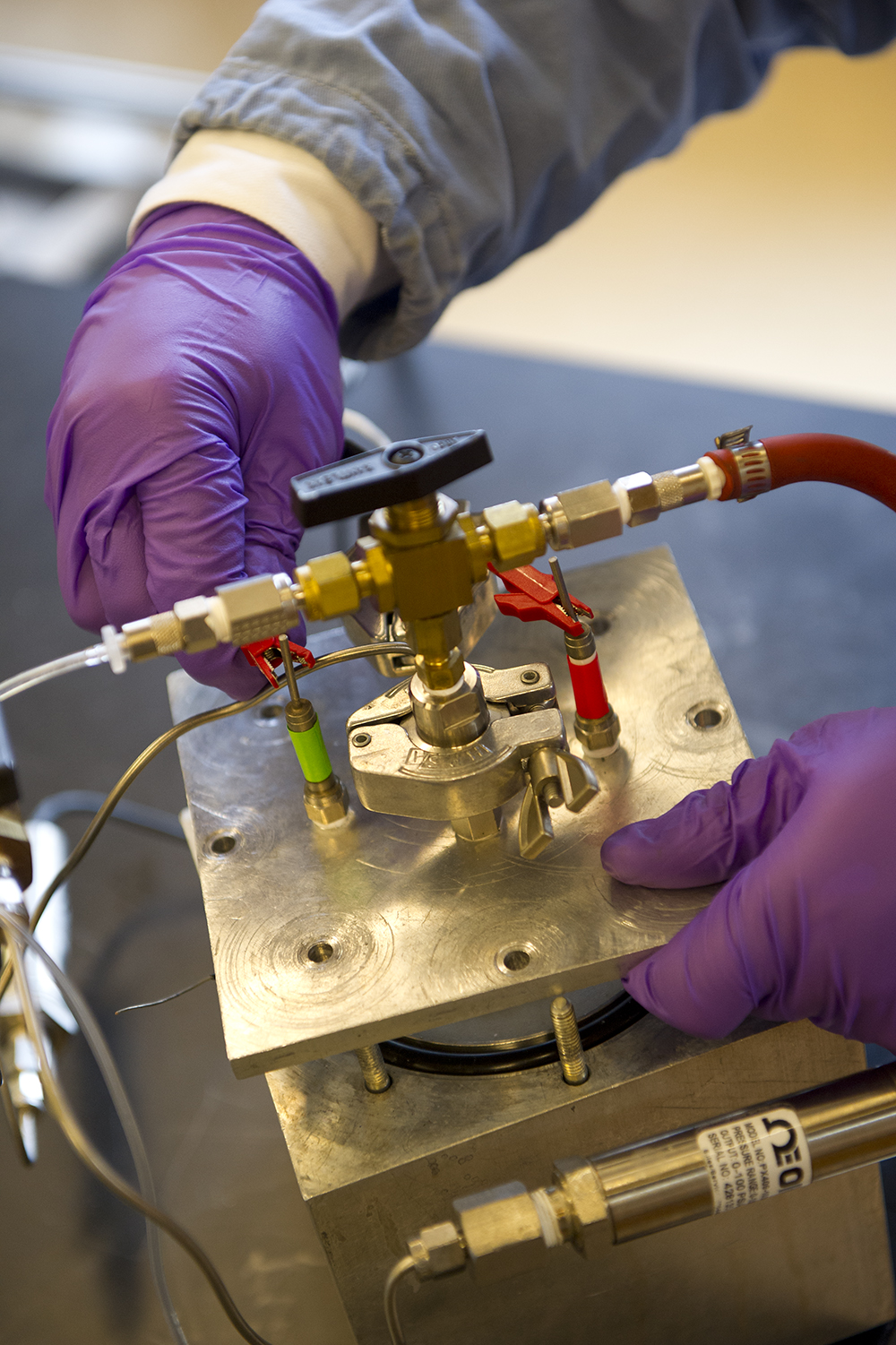
To test the behavior of their system, the researchers placed a single electrochemical cell inside a custom-made, sealed box and wired it for electricity input. They then cycled the voltage and measured the key responses and capabilities of the device.
The diagram below shows results from 10 cycles of voltage change. The top curve shows the charge density put into the cell, and the bottom curve shows how much CO2 was adsorbed per mole of quinone. The simultaneous trends show that when the quinone electrode is negatively charged, the amount of CO2 adsorbed goes up. And when that charge is reversed, CO2 adsorption declines.
For experiments under more realistic conditions, the researchers also fabricated full capture units—open-ended modules in which a few cells were lined up, one beside the other, with gaps between them where CO2-containing gases could travel, passing the quinone surfaces of adjacent cells.
In both experimental systems, the researchers ran tests using inlet streams with CO2 concentrations ranging from 10% down to 0.6%. The former is typical of power plant exhaust, the latter closer to concentrations in ambient indoor air. Regardless of the concentration, the efficiency of capture was essentially constant at about 90%. (An efficiency of 100% would mean that one molecule of CO2 had been captured for every electron transferred—an outcome that Hatton calls “highly unlikely” because other parasitic processes could be going on simultaneously.) The system used about 1 gigajoule of energy per ton of CO2 captured. Other methods consume between 1 and 10 gigajoules per ton, depending on the CO2 concentration of the incoming gases. Finally, the system was exceptionally durable. Over more than 7,000 charge-discharge cycles, its CO2 capture capacity dropped by only 30%—a loss of capacity that can readily be over-come with further refinements in the electrode preparation, say the researchers.
The remarkable performance of their system stems from what Voskian calls the “binary nature of the affinity of quinone to CO2.” The quinone has either a high affinity or no affinity at all. “The result of that binary affinity is that our system should be equally effective at treating fossil fuel combustion flue gases and confined or ambient air,” he says.
Practical applications
The experimental results confirm that the electro-swing device should be applicable in many situations. The device is compact and flexible; it operates at room temperature and normal air pressure; and it requires no large-scale, expensive ancillary equipment—only the direct current power source. Its simple design should enable “plug-and-play” installation in many processes, say the researchers.
It could, for example, be retrofitted in sealed buildings to remove CO2. In most sealed buildings, ventilation systems bring in fresh outdoor air to dilute the CO2 concentration indoors. “But making frequent air exchanges with the outside requires a lot of energy to condition the incoming air,” says Hatton. “Removing the CO2 indoors would reduce the number of exchanges needed.” The result could be large energy savings. Similarly, the system could be used in confined spaces where air exchange is impossible—for example, in submarines, spacecraft, and aircraft—to ensure that occupants aren’t breathing too much CO2.
The electro-swing system could also be teamed up with renewable sources, such as solar and wind farms, and even rooftop solar panels. Such sources sometimes generate more electricity than is needed on the power grid. Instead of shutting them off, the excess electricity could be used to run a CO2 capture plant.
The researchers have also developed a concept for using their system at power plants and other facilities that generate a continuous flow of exhaust containing CO2. At such sites, pairs of units would work in parallel. “One is emptying the pure CO2 that it captured, while the other is capturing more CO2,” explains Voskian. “And then you swap them.” A system of valves would switch the airflow to the freshly emptied unit, while a purge gas would flow through the full unit, carrying the CO2 out into a separate chamber.
The captured CO2 could be chemically processed into fuels or simply compressed and sent underground for long-term disposal. If the purge gas were also CO2, the result would be a steady stream of pure CO2 that soft-drink makers could use for carbonating drinks and farmers could use for feeding plants in greenhouses. Indeed, rather than burning fossil fuels to get CO2, such users could employ an electro-swing unit to generate their own CO2 while simultaneously removing CO2 from the air.
Costs and scale-up
The researchers haven’t yet published a full technoeconomic analysis, but they project capital plus operating costs at $50 to $100 per ton of CO2 captured. That range is in line with costs using other, less flexible carbon capture systems. Methods for fabricating the electro-swing cells are also manufacturing-friendly: The electrodes can be made using standard chemical processing methods and assembled using a roll-to-roll process similar to a printing press.
And the system can be scaled up as needed. According to Voskian, it should scale linearly: “If you need 10 times more capture capacity, you just manufacture 10 times more electrodes.” Together, he and Hatton, along with Brian M. Baynes PhD ’04, have formed a company called Verdox, Inc., and they’re planning to demonstrate that ease of scale-up by developing a pilot plant within the next few years.
This research was supported by an MIT Energy Initiative (MITEI) Seed Fund grant and by Eni S.p.A. through MITEI. Sahag Voskian SM ’15, PhD ’19 was an Eni–MIT Energy Fellow in 2016–2017 and 2017–2018. He is now co-founder and chief technology officer at Verdox, Inc. Further information about the research can be found in:
S. Voskian and T.A. Hatton. “Faradaic electro-swing reactive adsorption for CO2 capture.” Energy & Environmental Science, issue 12, 2019. doi.org/10.1039/c9ee02412c.
This article appears in the Spring 2020 issue of Energy Futures.