Overview
Devices from compressors to flywheels could be revolutionized if electric motors could run at higher speeds without getting hot and failing. MIT researchers have now designed and built novel motors that promise to fulfill that dream. Central to their motors are spinning rotors of high-strength steel with no joints or bolts or magnets. Rather than resting those rotors on vulnerable bearings, the researchers levitate them by manipulating the steel’s natural magnetic “memory” to control the magnetic fields inside the device. Their contact-free designs are compact, efficient, and suited to low-cost manufacturing as well as high-speed operation. One motor is specially designed as a high-velocity flywheel for reliable, fast-response energy storage—a function that will become increasingly important as electric power systems become more reliant on intermittent energy sources such as solar and wind.
As the world looks to limit greenhouse gas emissions, carbon-free renewable energy sources such as solar and wind will play a growing role on power grids. But such sources cannot generate electricity all the time. According to David L. Trumper, professor of mechanical engineering, a good way to smooth out supply would be using a high-performance version of an old energy-storage device: the flywheel. When sunshine and wind are abundant and electricity is plentiful, some power would be diverted into making the flywheel spin. When the sun sets or the wind dies down, the flywheel would be allowed to decelerate, running a generator that feeds electricity into the power system to fill the gap. The stored energy could also be used to meet occasional peaks in electricity demand—a far less expensive approach than the current practice of maintaining “peaking plants” that run only as needed. Flywheels are environmentally benign, quick to respond, long lasting, and insensitive to temperature changes. But they perform best when they turn at extremely high speeds—as do machines ranging from generators, compressors, and turbines to precision machine tools. What’s needed is a motor that can run safely and reliably with its rotor surface moving at several times the speed of sound.
Steps in the right direction
Designing a motor to turn electricity into movement is tricky. In a typical motor, a component called a rotor turns inside a stationary component called a stator. One of those components contains permanent magnets that have south and north poles. The other has wire coiled around it. Putting electricity through the coils creates magnetic fields that attract and repel the poles of the permanent magnets. That interaction causes the rotor to turn. Keeping it spinning requires constant changes in the magnetic fields. As Trumper explains, “The coil current has to vary in time so as to create moving magnetic fields that create the forces you want in the directions you want” to rotate the rotor.
In a conventional brushed direct-current motor, the magnets are in the stator and the coils go around the rotor. The rotor is supported by a pair of mechanical bearings. But those bearings tend to wear out—especially when the rotor spins quickly. So about 20 years ago, researchers developed a “self-bearing motor.” They moved the coils from the rotor onto the stator and the permanent magnets from the stator onto the rotor. By controlling the magnetic field from the stator, they could both levitate and turn the rotor. In this design, the entire motor consists of just the rotor plus the stator—no bearings needed. But there are still problems. Permanent magnets aren’t mechanically strong, so the magnets inserted into the rotor make the rotor vulnerable to failure when it spins fast. In addition, a complex, expensive monitoring and control system is needed to keep the rotor just the right distance from the stator—close enough to be kept from dropping but not so close as to be grabbed tight.
Combining existing technologies
To Mohammad Imani-Nejad PhD ’13, Trumper’s graduate student and now a postdoctoral associate in the MIT Laboratory for Manufacturing and Productivity, the solution was to get rid of the permanent magnets as well as the bearings. Instead of using permanent magnets, he would suspend and drive the rotor using a phenomenon called hysteresis. “Imagine that there’s a memory in the material,” explains Imani-Nejad. “If it’s in one state and then it’s switched, it takes a while to adjust to the new state.” If an external magnetic field is applied to, say, iron, then when the field is removed, the iron remains magnetized—until it’s exposed to a larger magnetic field in the opposite direction.
In a conventional motor, the hysteresis effect creates an energy loss, so engineers work hard to minimize it. In a hysteresis motor, however, it’s a useful mechanism. With careful controls, that lag in switching can cause the rotor—with its residual magnetization—to try to “catch up” with the present magnetic field of the stator; the rotor therefore turns with constant force, even when it’s first starting up. “Typically people try to avoid hysteresis,” says Imani-Nejad. “But here we welcome it. We want it to be larger.”
While self-bearing motors are relatively new, hysteresis motors have a long history, with early designs proposed about 100 years ago. But Imani-Nejad believes he’s the first to combine the two concepts. To support his novel idea, he first formulated new theoretical models of the forces involved and the control algorithms required. Guided by those calculations, he then designed, built, and tested three versions of his motor. While they differ in size and configuration, all share one critical feature: a smooth, solid rotor that contains no permanent magnets, joints, bolts, or laminations. It can be made of hard, high-strength steel in which the hysteresis effect is strong, and it can be shaped like a disk, an elongated cylinder, or any rotationally symmetric object—all well-suited to high-speed operation.
Novel designs
Hysteresis self-bearing motor
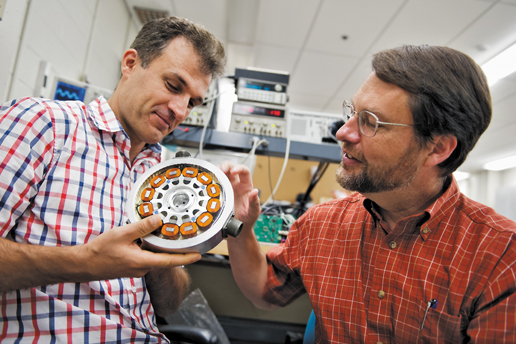
This photo shows the MIT researchers’ first motor designed to run at high speeds, free of both bearings and permanent magnets. The rotor at the center is solid, high-strength steel, with no joints or magnets to weaken it. Rather than resting on bearings, it is levitated by the stator above it. Electricity running through coils of wire on that stator produces magnetic fields that magnetize the steel of the rotor—an effect that can be manipulated to keep the rotor suspended, stable, and spinning. The unusual “sandwich” arrangement permits the researchers to keep the rotor at a constant distance from the stators above and below, even when currents are high and when centrifugal forces cause the rapidly spinning rotor to stretch. Photo: Mohammad Imani-Nejad PhD ’13
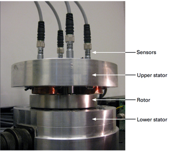
The photo to the right shows the first setup they built. It consists of a rotor sandwiched between two stators, top and bottom. Four sensors entering from the top monitor the position of the rotor, including any tilt and tip. Power amplifiers and other controllers respond by adjusting the current in the coils to keep the rotor suspended, stable, and spinning.
The sandwich approach brings several advantages. During high-speed operation, a strong centrifugal force will cause the rotor to expand—by as much as a few millimeters. In most motors, the rotor spins inside the stator—a sort of tube within a tube. When the rotor expands, the gap between the stator and rotor changes significantly, and the performance of the motor deteriorates. In contrast, the MIT design rotates a flat steel disk. Steel is generally viewed as strong and solid, but the design calls for the outside of the rotor to move at 500 meters per second. “In this domain—under this stress—it’s like it’s made of rubber,” says Trumper. So it responds to centrifugal forces and stretches—like pizza dough does when it’s spun. But because the rotor gets wider rather than taller, the distances to the stators above it and below it remain approximately constant.
A second benefit of the sandwich configuration is the potential for higher power. In demonstrations, the researchers showed that they could both levitate and rotate the rotor with a single stator above it. But with just one stator, there’s a limit to how much current they can pass through the coil before the rotor is yanked up against the surface of the stator. The lower stator enables them to create forces that pull the rotor down, away from top stator. By carefully balancing the upward and downward forces, they can further increase the current and thereby increase the torque—the force with which the rotor turns—to get more acceleration and more power out.
Windings and stators
With any motor, a major challenge is designing the coils and the currents they carry to create the magnetic fields needed to control the rotor. Methods of making coils for motors with permanent magnets are well understood, but Trumper and Imani-Nejad needed to depend on hysteresis—a far greater challenge. Guided by his theoretical analyses, Imani-Nejad designed three sets of coils that turn the rotor plus another set that levitates it. His “multiple winding hysteresis motor” performs well. Over time, movement of the rotor stabilizes in some directions, but in others it must be actively controlled by measuring its position some 10,000 times a second and then changing the currents in the coils to control that position. “And it’s all done without contact, by the magnetic fields,” stresses Trumper.
Segmented stator
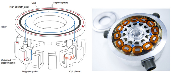
Photo: Stuart Darsch
In another of his hysteresis motors, Imani-Nejad redesigned the upper stator itself. He divided it into 12 U-shaped electromagnets, or “cores,” as shown in the diagram and photo above. He then wrapped a single coil around each core, thereby replacing the complicated collection of over-lapping coils. In this design, the magnetic pathway in the stator is shorter. Instead of having to travel from one side of the stator to the other, the pathway just runs up and down each of the U shapes. Energy losses are reduced, and motor efficiency is increased. In addition, the coils are easily wound and take up little space, so the segmented stator should be less expensive to manufacture than conventional stators are.
Focus on flywheels
When it comes to flywheels, the best design has a rotor that spins fast and is very tall—a long cylinder with lots of inertia. Imani-Nejad’s design for such a machine appears below. (The stators are not shown in the diagram.) It retains the sandwich arrangement with stators above and below the rotor, which is a tall cylinder made in part of a hysteresis material. Because of its shape, this rotor does not tend to tip or tilt but is unstable in just one direction—up and down. To support it, Imani-Nejad added pairs of permanent magnets at the top and the bottom. In both locations, one magnet is on the stator, the other at the end of the rotor.
Flywheel design
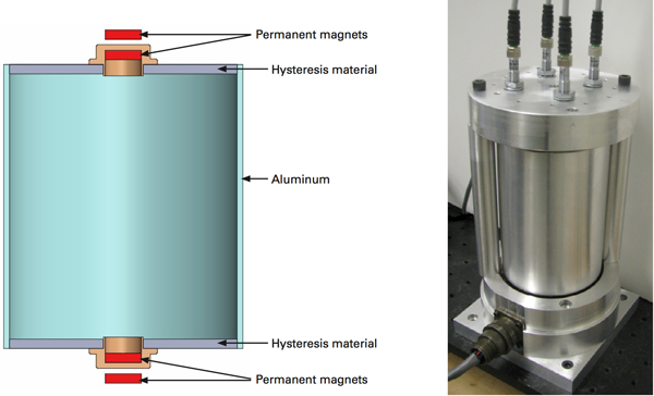
Photo: Mohammad Imani-Nejad PhD ’13
The forces created by those magnets compensate for about 99% of the rotor’s weight, with the stators providing the remaining support. “We adjust the current to levitate it to make the system stable, but we only need to control for about 1% of the weight of the rotor,” says Imani-Nejad.
When they ran this new motor at 600 rpm, they found that the rotor stayed about half a millimeter away from the stators above and below, shifting by no more than 50 microns. Best of all, they could run it with a simple control system—without the dozen or more sensing and actuating elements generally required to run self-bearing motors. “We showed theoretically and experimentally that with the right controller you can make this system stable by controlling movement along just one axis,” says Imani-Nejad. “That makes it much less expensive and much less complicated—and very interesting for real-world applications.”
Thus far, the fastest they’ve run any of their motors is at 10,000 rpm—appropriate for proof-of-concept demonstrations but not nearly the speeds needed to test for real applications. According to Trumper, it’s also nowhere near the speed range that they could do. But they can’t yet safely test at high speeds. “To go to those high speeds, you have to build a vacuum system and a proper containment vessel so if you do fail a rotor, it’s not hazardous to the people in the lab,” he says. “But the physics is such that these motors are capable of running at those speeds. We haven’t proven it yet experimentally, but with the right equipment, we know we could do it.”
This research was supported by a seed grant from the MIT Energy Initiative and by ABB. Further information can be found in:
M. Imani-Nejad. Self-Bearing Motor Design & Control. PhD thesis, MIT Department of Mechanical Engineering. February 2013.
This article appears in the Autumn 2013 issue of Energy Futures.